8 Bit Serial To Parallel Converter Verilog Code
Rewrite iso PPSSPP Posted on November 14, 2018 November 14, 2018 by love Rewrite apk android for ppsspp iso rom cso free download working on mobile and pc,Rewrite is about Tennouji Kotarou, a young man who is in high school. Rewrite Is a Japanese visual novel developed by Key, a brand of VisualArt’s. It was released on June 24, 2011 for Windows PCs and is rated for all ages. The Walkthrough is included in the translation patch and will be found in the game folder. Abc1.ISO ←Disc1のイメージファイル abc2.ISO ←Disc2のイメージファイル ファイル名変更後 abc.ISO ←Disc1のイメージファイル abc1.ISO ←Disc2のイメージファイル 5.ファイル名を変更したらメモリースティックをスリープモードで待機させているPSPに挿入. Rewrite psp iso download. [PC][他の女の子とHをしているオレを見て興奮する彼女 ]ISO (JPN) MDF Download [PS3][バイオショック インフィニット コンプリートエディション ] (JPN) ISO Download.
Figure 6: Serial-to-Parallel IC chip The basic idea is to send a sequence of bits (i.e., positive pulses) down to the serial-to-parallel chip (74HC595). The 74HC595 will then convert this serial input into a parallel input and latch the output so it continues to drive the LED display until the next series of bits is received and latched. This operation, however, requires some degree of control. For instance, we need some way of telling the chip when the pulses are expected to occur and we need some way of telling the chip when to latch the data. This means that we need two control lines to the chip, in addition to the data line. To understand how these control lines work, we need to take a closer look at how the 74HC595 functions.
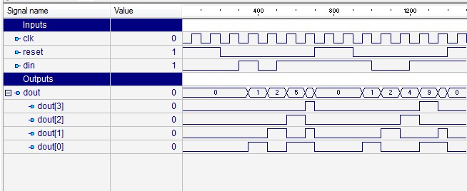
Verilog code for converting serial data to parallel. The 8-bit serial data from rs232 port is converted to 8-bit parallel data.
The 74HC595 consists of an interconnected set of simpler digital circuits known as latches. There are actually two banks (columns) of latches, each column consisting of 8 latches. Figure shows these two columns. The first column of latches form something known as a shift register. This bank accepts the serial input and shifts each bit in the series of input pulses down into the column. The second column of latches is used to store what is in the first column.
This second column is connected to the chip's output and is used to drive the LED display. This frees up the first column to receive another series of inputs, without disrupting the actual signals delivered to the 7-segment display. Figure 7: Timing diagram for the serial-to-parallel chip Each latch is a digital circuit with two inputs and one output.
The right place to find all older Star pistol model numbers is on the butt, as seen in the illustrations below and photo to the right. On the flat plate on the bottom of the gun, just rear of where the magazine is inserted, look for a letter, set of letters or a word. The longer number is your serial number, incidentally. Star pistol serial numbers.
The top input with the black arrowhead represents the data and the other input with the white arrowhead represents a control. The lines with the black arrowhead are connected to the pin marked SER (serial input) and the lines with white arrowheads are connected to the pin marked SRCLK. This line is sometimes called the clock line. When the data line (SER) is high and the control (SRCLK) is high, then the output of the latch is also high until it is reset. When the data (SER) is high and the control (SRCLK) is low, then the output does not change from its previously latched value. The first column of latches are daisy chained together so the output of the top latch is the data input to the second latch.
What we do, therefore, is input a bit string into SER along with a SRCLK signal. Each time SRCLK goes high, the data in a latch is shifted to the latch below it. We can therefore enter a string of 8 bits into the first column of latches by sending each bit along the SER line and then setting the SRCLK line high for each bit of data. The timing diagram shown in figure shows how the bit string 1011 is shifted into the device. After the data has been shifted into the first column, we transfer this data in parallel to the second column of latches by setting the RCLK line high. This second column of latches will retain their value until we overwrite them with another RCLK signal.